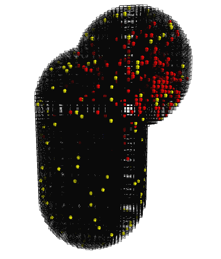
If the visualiser is enabled, it will render an approximation of the system. A screen shot is provided in Figure 5.3, “ The OpenGL Visualiser ”. There are a few commands to control the visualiser.
Moving the mouse while pressing the left mouse button will rotate the system. Rotation is a little counterintuitive compared to how rotation works in other visualisers.
Moving the mouse while pressing the left mouse button and holding down the Ctrl key will move the slabbing plane backwards and forwards along the
z-axis. This adjusts how much of thez-axis extent of the geometry will be rendered.Moving the mouse while pressing the left mouse button and holding down the shift key will move the camera backwards and forwards along the
z-axis. This is equivalent to zooming.Pressing the G key toggle display of the grid. The grid is what marks the individual sub volume boundaries.
Pressing the C key toggle display of the connectors. The connectors are arrows between sub volumes that are topologically connected. This feature is intended for debugging, mostly.
The Visualiser versus The Absolute Truth
The visualiser cannot be trusted to give a
completely accurate picture of the system.
One multiprocessor systems, the visualiser will typically run on
its own CPU, while the simulation itself runs elsewhere. Thus
the system may change while the visualiser is rendering it, and
the instantaneous picture as seen on the screen may actually be
a blend of one ore more simulation steps. Furthermore, the
number of molecules in a sub volume is typically much larger
than what can be displayed. When rendering a subvolume, the
visualiser will cycle through the different species in the sub
volume, rendering one molecule of each species in every cycle.
If there are no molecules of a certain species, the visualiser
proceeds to the next. Thus, if there were one thousand
A molecules and only one B
molecule in the sub volume, but the visualiser could fit eight
molecules into a sub volume, the sub volume will be rendered
containing seven A molecules and one
B molecule.
